If you’ve ever owned an acoustic guitar that you love, but want to add electronics to it for live performances or recording applications, you will have noticed a booming industry full of rather expensive products. Having a very limited grasp on electrical circuits and the technologies used in these products, I am convinced that they are criminally overpriced, so I decided to experiment. I am actively documenting this project as it evolves, so let’s start at the beginning.
Inspiration
The LR Baggs Anthem seems to be the most popular retail product in this category. Being a lifetime musician, I have used numerous different undersaddle, magnetic pickup, and microphone products similar to this. My own acoustic guitar has a Martin Thinline undersaddle piezo installed, along with a Skysonics mag/mic combo I bought on AliExpress. It sounds surprisingly good for what it is, but I’m not convinced all that gadgetry is necessary. Anyway, back the the LR Baggs system.
Here is what I can tell this system is made up of:
- Some sort of under-saddle piezo wire/rod
- A patented TRU-MIC, which appears to be a standard piezo disc encased in plastic.
- An endpin jack
- Battery compartment
- A preamp that mounts in the sound hole

For a whopping $299 USD, that seems like a pretty scant list of ingredients. This parts list seems a lot more in the neighborhood of $20-50. Take into consideration that most musicians will end up hiring a luthier or guitar tech to install it for them for an additional price, and you can understand why my mind went to reinventing the wheel.
Musicians deserve to know the truth, and that truth is that piezoelectric pickups that these systems use cost mere cents to manufacture. On top of that, there is no voodoo in the circuitry. Being powered by a 9v battery, my mind immediately goes to a few purpose-built op-amps sold for cents by Texas Instruments, and the correct network of resistors and capacitors to correctly bias the piezo’s ultra-high impedance. Throw in some more cheap components if the manufacturers thought at all about including protection diodes in the event the sensitive piezo element is thwacked hard enough to damage the op-amp.
Research
Whenever I consider a problem, I typically assume someone has already done a much more thorough job of solving it than me. This lead me down the search rabbit-hole for a decent piezo element preamp. I have maybe a hundred little cheap piezo discs of various sizes laying around, so I decided I would base my own design around these cheap and easy-to-find components.

I should mention at this point that these cheap components likely aren’t to the same caliber as the LR Baggs under-saddle piezo or TRU-MIC, but they probably aren’t as far off as one might think. A piezo element is a pretty simple device.
While I had initially thought of an op-amp/battery combo, I found this YouTube video, which was intriguing since it only used a 3 volt coin cell battery source. I liked the idea of making my own design as small as possible with no frills, so I based my circuit design almost exactly off of this.
Design
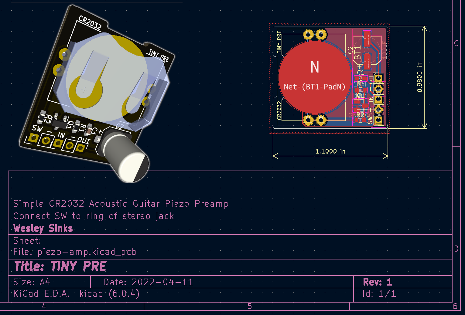
Here is the schematic I drew up quickly in KiCad:

Admittedly, I should have done a little more digging before designing this circuit. More on that later, but I went for it, found all the tiny surface-mount components I could, and designed the board. Here is what I came up with - a circuit roughly the size of a postage stamp.

Eager to build something and prove how corrupt predatory capitalism has become, I hastily ordered all the parts and boards I would need to build 5 of these. Why 5? Well, because that is the minimum amount of PCB’s you can order from JLCPCB. Since submitting an order for parts didn’t thoroughly stifle my curiosity, I then stumbled on what I believe to be the best design for a piezo disc preamp, so now I have some ideas for revision 2 whether this version works well or not.
Update 4/18/2022: More Options
I also happened across this rather interesting read in my quest. I will have to look into it further along with the robust op-amp design linked above if I continue to revise this project into a second version.*
That’s all for now! I’ll update this post once the parts and boards arrive, and I am able to test them out.
Update 5/10/2022: Borkt
I received the PCB’s for the original design shown above, and sadly, it did not work! I tried powering it with the 3v3 coin cell, as well as 5v and 9v sources with no luck. I likely messed something up with the ground/power here. I might try bodging it into a working state with some diodes next. If that fails, I’ll begin designing a PCB based on one of the other articles linked just above. Stay tuned. If you have any questions about this project or would just like to chat, head on over to my public live chat.